


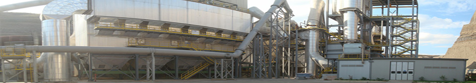

Design and Management of the project

AMC Glass Ltd (GTE Holding) gives to the customers all the technological engineering supports, to permit them, to choose the most efficiency glass factory (or production line) shapes and configuration.
|
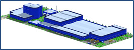
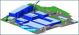
WE SUPPLY TECHNOLOGICAL AND NETWORK PROJECTS FOR THE FOLLOWING:
|
    |
 |
SCOPE OF SUPPLY
-
Preliminary project
Visit on site to collect the necessary information
Technical and commercial documentation
- Brief description of the project and of the complete factory
- Detailed investment budget plan including foreign and local equipments
- Production cost calculation and profitability
- Project execution time table
- Table of personnel required in the factory with specialization
- Suggested batch composition for green and flint glass to start up the plant
- Furnace gas emission specification
- Energies and water consumption table
- Equipment specification in order to receive quotation from Suppliers
Technological drawings
- Factory general lay out based on territory topographic map and other buildings already existing on site
- Raw materials storage lay out
- External cullet storage, washing and cleaning lay out
- Dosing and mixing line layout, longitudinal section and cross section
- Batch transport to the furnace lay out
- Cold and hot cullet recovery system lay out
- Production building at furnace regenerators level with equipment positioning
- Production building at production level with equipment positioning
- Production building at feeder level with equipment positioning
- Production building longitudinal section
- Production building cross section
- Compressor, vacuum room layout with equipment positioning including cooling towers
- Electrical distribution preliminary scheme for the technological equipments
- Laboratories, maintenance workshops, spare parts warehouse and offices layout
- Production building architectonic preliminary drawing
- Finish product warehouse layout (based on existing situation)
Visit on site to present the preliminary project and agreed possible modification with the customer
-
Batch plant technological project
Technological documentation
- General layout drawings at necessary levels with equipments positioning
- Storage area for raw material drawings
- Batch plant longitudinal section drawings
- Batch plant cross section drawings
- Batch plant levels columns positions
- Batch plant levels load and explanations
- Layout drawings with raw materials preparation equipments positioning
- Layout drawings with raw materials transport to the silos equipments positioning
- Layout drawings with dosing, transport to the mixer and mixing equipments positioning
- Layout drawings with batch transport to the furnace equipments positioning
- Layout drawings with batch plant auxiliaries equipments positioning
- Layout drawings with internal cullet storage and dosing equipments positioning
- Layout drawings with external cullet preparation, storage and dosing equipments positioning
Technical economical documents that will be supply
- Project time table
- Batch receipt for any type of glass
- Energies consumption table for technological process (Gas, Electrical, Ventilated air, Compressed air, Vacuum and Water)
- List of technological equipments required in the process.
-
Production building technological project
Technical documentation
- Technological General layout drawings at regenerators level, with equipments positioning
- Technological General layout drawings at production level, with equipments positioning
- Technological General layout drawings at feeder level, with equipments positioning
- Production plant longitudinal section drawings
- Production plant cross section drawings
- Layout drawings with furnace and chimney positioning
- Layout drawings with regenerators foundation and loading on foundation
- Layout drawings with furnace foundation and loading on foundation
- Layout drawings with furnace auxiliaries equipments positioning and loading on foundation
- Layout drawings with cooling furnace water system equipments positioning and loading on foundation
- Layout drawings with working end and forehearths positioning and loading on foundation
- Layout drawings with working end and forehearths auxiliaries equipments positioning and loading on foundation
- Layout drawings with IS machine positioning and loading on foundation
- Layout drawings with IS machines auxiliaries equipments positioning and loading on foundation
- Layout drawings with hot cullet scraper equipment positioning and drainage schematic layout
- Layout drawings with annealing lehrs positioning
- Layout drawings with cold end equipments positioning
- Layout drawings with inspection machine equipments positioning
- Layout drawings with packaging equipments positioning
- Layout drawings with cold cullet recovery system equipments positioning
- Layout drawings with batch plant tunnel connection for the furnace
Air compressors and vacuum pumps room
- Technological General layout drawings air compressors room equipments positioning
- Technological General layout drawings vacuum pumps room equipments positioning
- Air compressors and vacuum pumps room longitudinal section drawings
- Air compressors and vacuum pumps room cross section drawings
- Layout drawings air compressors and auxiliaries equipments positioning
- Layout drawings with low pressure compressors water cooling system equipments positioning
- Layout drawings vacuum pumps and auxiliaries equipments positioning
Transformer electrical room
- Technological General layout drawings with electrical transformer positioning
- Technological General layout drawings with electrical transformer auxiliaries equipments positioning
- Electrical distribution panels room with equipments positioning
Technical economical documents that will be supply
- Detailed investment budget and monthly cash flow
- Project time table
- Furnace technical specification
- Energies consumption table for technological process (Gas – Electrical – Ventilated air – Compressed air – Vacuum and Water)
- List of technological equipments required in the process
-
Batch plant network project
Batch plant building networks
- Gas piping network drawings for raw materials dryer (indicating the pipes type and diameters, flange connections, valves etc.)
- Compressed air piping network drawings for raw materials preparation, dosing and mixing line (indicating the pipes type and diameters, flange connections, valves etc.)
- Aspiration piping network drawings for raw materials preparation, dosing and mixing line (indicating the pipes type and diameters, flange connections, valves etc.)
- Water piping drawings for raw materials preparation, dosing and mixing line (indicating the pipes type and diameters, flange connections, valves etc.)
- Fire fighting piping drawings for raw materials preparation, dosing and mixing line (indicating the pipes type and diameters, flange connections, valves etc.)
- Preliminary electrical system drawings (indicating the installed power for each equipments and connection points etc.)
- Complete bill of material needs for the installation, indicating:
- necessary pipes quantity (for each type and diameter)
- necessary bends quantity (for each type and diameter)
- necessary valves quantity (for each type and use)
- necessary flanges quantity (for each type and use)
- necessary pipes supports
-
Production building network project
Production building networks
- Gas piping network drawings for production plant equipments connections (indicating the pipes type and diameters, flange connections, valves etc.)
- Compressed air piping network drawings for production plant and batch plant additional equipments connections (indicating the pipes type and diameters, flange connections, valves etc.)
- Ventilated air piping network drawings for production plant equipments connections (indicating the pipes type and diameters, flange connections, valves etc.)
- Vacuum air piping network drawings for production plant equipments connections (indicating the pipes type and diameters, flange connections, valves etc.)
- Industrial water piping drawings for production plant and batch plant additional equipments connections (indicating the pipes type and diameters, flange connections, valves etc.)
- Softened water piping drawings for production plant equipments connections (indicating the pipes type and diameters, flange connections, valves etc.)
- Complete bill of material needs for the installation, indicating:
- necessary pipes quantity (for each type and diameter)
- necessary bends quantity (for each type and diameter)
- necessary valves quantity (for each type and use)
- necessary flanges quantity (for each type and use)
- necessary pipes supports
Air compressors and vacuum pumps room networks
- Compressed air piping network drawings for compressor room equipments connections (indicating the pipes type and diameters, flange connections, valves etc.)
- Vacuum air piping network drawings for vacuum pumps room equipments connections (indicating the pipes type and diameters, flange connections, valves etc.)
- Industrial water piping drawings for compressor room equipments connections (indicating the pipes type and diameters, flange connections, valves etc.)
- Softened water piping drawings for compressor room equipments connections (indicating the pipes type and diameters, flange connections, valves etc.)
- Complete bill of material needs for the installation, indicating:
- necessary pipes quantity (for each type and diameter)
- necessary bends quantity (for each type and diameter)
- necessary valves quantity (for each type and use)
- necessary flanges quantity (for each type and use)
- necessary pipes supports
-
Existing batch plant modification, upgrading or extension
- Raw materials treatment system modification and upgrading
- Raw materials transport system modification and upgrading
- Additional raw materials receiving, treatment system and transport
- Raw materials storage system modification and upgrading to improve the storage period
- Dosing and mixing line modification and upgrading to improve the production capacity
- Dosing and mixing line modification and upgrading to produce additional type of glass
- Dosing and mixing line modification and upgrading to reduce the production losses
- Aspiration and filter system modification and upgrading to improve the working environment
- External cullet receiving, treatment and dosing system modification and upgrading
- Internal hot and cold cullet return system modification
and also Batch plant complete reconstruction project
-
Production building and auxiliaries rooms modification, upgrading or extension
- Technological and network project to increase the furnace production capacity
- Technological and network project to add production lines on existing furnace
- Technological and network project to upgrade and / or modify existing production lines
- Technological and network project to add air compressors on existing air compressors room
- Technological and network project to add vacuum pumps on existing vacuum room
- Technological and network project to upgrade and / or modify existing cold end and / or packaging lines
- Technological and network project to upgrade and / or modify existing inspection machines lines
- Technological and network project to upgrade and / or modify existing auxiliaries rooms
and also Production building and auxiliaries rooms complete reconstruction project
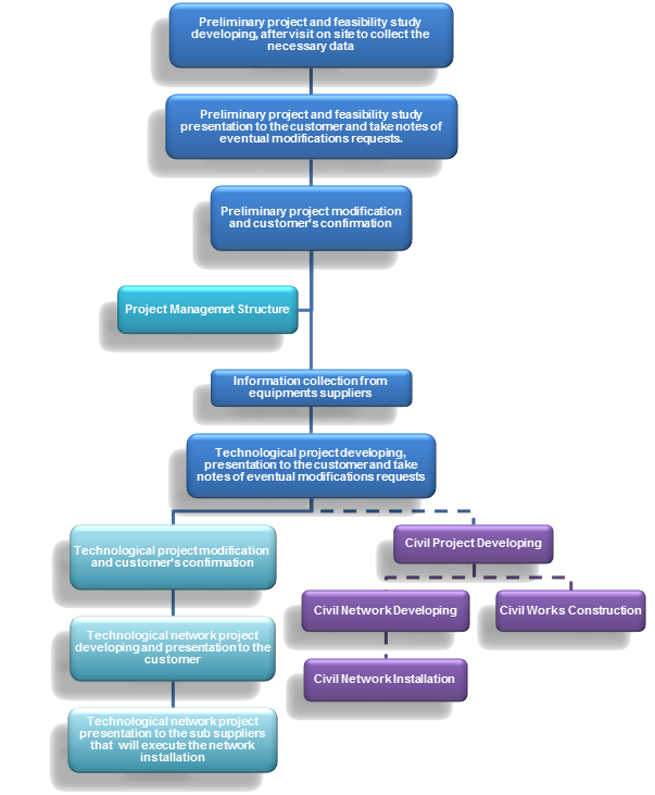
AMC Glass Ltd (GTE Holding) supply a Project Management Structure to give a full assistance to the customer during the project developing period and up to the production start up, having the following tasks:
- Present and discuss with the customer the projects under scope of supply.
- Check and discuss with the customer the other projects involved in the full engineering.
- Supply all the technical characteristics for the equipments required at the local suppliers and to support the customer with technical and commercial assistance during the negotiations with the local suppliers.
- Support the customer with technical and commercial assistance during the negotiations with the foreign suppliers.
- Supply all the necessary technical documentation in order to get the local permits and certificates.
- Manage the relationships with the local corporate body in order to get the necessary permits and certificates.
- Prepare the detailed projecting works schedule.
- Check and compare the equipments technical specifications offered by the different potential suppliers, in order to choose the most convenient solutions.
- Check and inspect the technological metal structures supply by the local companies.
- Check and inspect the furnace refractory materials on the suppliers premises.
- Check and inspect the equipments at the suppliers premises.
TECHNOLOGICAL PROJECT DEVELOPMENT